|
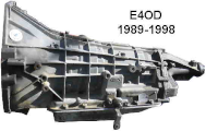
E4OD Transmission Testing |
|||||||||||||||||||||||||||||||
| A. | Checking for Computer Codes OBD-I / IEEC-IV (1989 - 1995) | ||||||||||||||||||||||||||||||
| B. | Checking for Computer Codes OBD-II / IEEC-V (1996 - 1998) | ||||||||||||||||||||||||||||||
| C. | E4OD sensors: (1989 - 1998) | ||||||||||||||||||||||||||||||
| A. | Checking Computer Codes OBD-I / IEEC-IV (1989 - 1995) | ||||||||||||||||||||||||||||||
| Perform the Key On Engine Off (KOEO) self test. | |||||||||||||||||||||||||||||||
| 1. | Connect jumper and (optional test light or volt meter) as described in Figures OBD-1 A & B below. | ||||||||||||||||||||||||||||||
| NOTE: Turn off A/C during this test. | |||||||||||||||||||||||||||||||
| 2. | Turn Key off, then on, then off, then on, then off, back on | ||||||||||||||||||||||||||||||
|
ON - OFF - ON - OFF - ON - OFF - ON |
|||||||||||||||||||||||||||||||
| 3. | Display pulse codes will now show on instrument panel "Check Engine Light" and optional test light / volt meter. | ||||||||||||||||||||||||||||||
| Deleting Codes from Computer Memory: | |||||||||||||||||||||||||||||||
| 1. | Start KOEO test as described above. | ||||||||||||||||||||||||||||||
| 2. | Remove Jumper from from test connector once light begins to flash. | ||||||||||||||||||||||||||||||
| Codes should now be erased from Keep Alive Memory in computer. | |||||||||||||||||||||||||||||||
| Resetting Computer and Clearing Keep Alive Memory: | |||||||||||||||||||||||||||||||
| 1. | Disconnect battery for minimum of five (5) minutes. | ||||||||||||||||||||||||||||||
| Keep Alive Memory should now be cleared. | |||||||||||||||||||||||||||||||
| 2. | Vehicle must be driven for at least 10 miles of normal shifting driving on local and highway for OD so computer will relearn proper control based on sensor data. | ||||||||||||||||||||||||||||||
| 3. | Conduct all recommended sensor and electronic transmission tests. | ||||||||||||||||||||||||||||||
| Using "Check Engine Light" to read computer pulse codes - | |||||||||||||||||||||||||||||||
| Install jumper wire From test connector to Pin 2 on of computer connector as shown in figure OD1-A below. | |||||||||||||||||||||||||||||||
|
FIGURE OBD-1 A |
|||||||||||||||||||||||||||||||
|
|
|||||||||||||||||||||||||||||||
| Using Test Light or Analog Ohm Meter (with sweep needle - Not a digital meter) | |||||||||||||||||||||||||||||||
| Install jumper wire from test connector to Pin 2 on hook up connector; and Install test light or volt meter + lead to battery + terminal and - lead to Computer Connector as shown in figure OD-I B below. |
|||||||||||||||||||||||||||||||
|
FIGURE OBD-I B |
|||||||||||||||||||||||||||||||
|
|
|||||||||||||||||||||||||||||||
| Back to Top | |||||||||||||||||||||||||||||||
| B. | Checking for Computer Codes OBD-II / IEEC-V (1996 - 1998) | ||||||||||||||||||||||||||||||
| This requires using a Scantool Reader to read and display codes from the IEEC-V computer | |||||||||||||||||||||||||||||||
| At least one major Automotive Parts Chain loans a scantool to customers (Deposit required) | |||||||||||||||||||||||||||||||
|
|||||||||||||||||||||||||||||||
| Back to Top | |||||||||||||||||||||||||||||||
| C. | E4OD sensors: | ||||||||||||||||||||||||||||||
|
|||||||||||||||||||||||||||||||
| Checking for bad sensor or connector: | |||||||||||||||||||||||||||||||
| 1. | Check each connector condition and for good contact. Connectors under vehicle can be contaminated with water, mud, etc. Clean connector contacts with contact cleaner and emery board (fiber finger nail file) as needed. |
||||||||||||||||||||||||||||||
| 2. | Visually inspect each wire for breaks from sensor back to firewall bulkhead connector. | ||||||||||||||||||||||||||||||
| 3. | Run continuity test on wires from sensor to bulkhead connector at firewall. Refer to proper vehicle wiring diagram to located appropriate pins on connectors and color of wire to trace. NOTE: Disconnect sensor connector and negative cable on battery prior to using a ohm meter as they have current which could damage the vehicle computer. Insert sharp probe in to wire near bulkhead connector and check for continuity at sensor connector. You may have to use a long piece of wire to do the continuity test. Repeat test for each wire. |
||||||||||||||||||||||||||||||
| 3. |
Adjust TPS or FIPL sensor per manual instructions for your particular vehicle If you have a Black colored FIPL sensor, replace this sensor with a Gray colored update. |
||||||||||||||||||||||||||||||
| 4. | Adjust the MLPS by aligning notices in shifter shaft with alignment notch in side (toward top) of sensor. Also, shift to Neutral and verify mark on MLPS is aligned properly. (not all after market makers of the MLPS use this neutral position mark). |
||||||||||||||||||||||||||||||
| Back to Top | |||||||||||||||||||||||||||||||


